In industrial flow measurement, “the right meter” is never a one-size-fits-all decision. The best choice is the one that meets your accuracy needs in your real piping conditions, for your real fluid, at your real operating temperature and pressure—without creating unnecessary maintenance burden or lifecycle cost.

At Jade Ant Instruments, we’ve seen that most “flow meter problems” are not product problems; they’re selection and installation problems. This guide turns the classic selection logic into a field-ready checklist that you can use for water, chemicals, steam, oil, and mixed industrial applications.
Internal reference (brand site):
Learn more about our instrumentation solutions at www.jadeantinstruments.com
01. Performance Requirements (What the Meter Must Deliver)
1) Decide: Rate (Instantaneous Flow) vs Total (Cumulative) vs Both
Before comparing technologies, define the business outcome of measurement:
- If you need custody transfer, batching, or material balance, totalized flow (cumulative) is usually the core.
- If you need process control, ratio blending, or dynamic regulation, stable and fast rate measurement (instantaneous flow) dominates.
Many modern meters can do both, but their “native strengths” differ:
- Positive displacement (PD) and turbine meters naturally produce pulses suitable for totalization.
- Electromagnetic and ultrasonic meters often excel in fast response for control loops and can also totalize via transmitter functions.
Practical rule:
If your flow value will be used to open/close valves and tune control loops in real time, prioritize response time and stability; if it will be used for billing or custody transfer, prioritize long-term accuracy stability and verification methods.
2) Accuracy vs Repeatability vs Linearity (Stop Mixing These Up)
- Accuracy tells you how close you are to the true value under specified conditions.
- Repeatability tells you how consistently the meter reads the same flow under unchanged conditions.
- Linearity describes how well accuracy holds across the whole range.
Why this matters:
- In control systems, repeatability often matters more than absolute accuracy because the controller reacts to changes.
- In custody transfer, accuracy (and how it is proven over time) is the core.
Industry reality check:
A published accuracy spec is typically conditional. Field performance can degrade due to flow disturbances, fouling, gas entrainment, installation stress, or signal noise. That is why “installation” is not a separate step—it’s part of meter performance.
Industrial expert insight (installation/straight-run importance):
Many metering errors originate from upstream disturbances and insufficient straight runs; standards and manufacturers repeatedly emphasize installation conditions as part of the measurement method, not an afterthought. A common reference for differential-pressure primary elements is ISO 5167, which explicitly defines geometry and “method of use (installation and operating conditions)” for devices such as orifice plates and Venturi tubes. Source
3) Range and Turndown (Upper/Lower Flow Limits)
Turndown (rangeability) is the ratio of maximum to minimum measurable flow with acceptable uncertainty. A meter that looks “wide range” on paper may still be impractical if the minimum velocity is too high for your operating reality.
Selection logic you can actually use:
- First estimate your normal flow window (Qnormal min to Qnormal max), not just design max.
- Then verify the meter can operate with acceptable uncertainty at low-flow conditions (startup, night shift, reduced load, etc.).
- Finally, confirm that high-flow will not trigger cavitation (liquids) or excessive pressure loss.
Typical engineering velocity guidance (rule-of-thumb):
- Low-viscosity liquids: economic velocity often ~1.5–3 m/s
- High-viscosity liquids: often ~0.2–1 m/s
(These are planning values; final selection must reference your process constraints.)
4) Pressure Loss (Hidden Cost That Keeps Charging You)
Permanent pressure loss is not just a performance detail; it is an energy bill. Differential-pressure elements and many mechanical meters inherently create pressure drop. Full-bore electromagnetic and some ultrasonic designs can approach near-zero pressure loss.
Decision trigger:
If your pipe is large (high flow) and pumping energy is a major cost driver, pressure loss can dominate lifecycle cost over purchase price.
5) Output Signal and Integration (Pulse, 4–20 mA, Digital)
Define how the signal will be used:
- 4–20 mA: common for control integration
- Pulse output: excellent for totalization and high-resolution counting
- Digital protocols (varies by transmitter): best for diagnostics, density/temp compensation, and data history
If your flow data goes long distance or into a metering computer/SCADA, plan for:
- signal integrity (shielding/grounding)
- power supply stability
- electromagnetic interference immunity
6) Response Time (Especially for Pulsating or Unsteady Flow)
If your flow is pulsating (positive displacement pumps, reciprocating compressors, cycling control valves), a meter may “read the pulses” instead of the average. Some solutions require damping, flow conditioning, or installing the sensor away from pulsation sources.
Quick sanity check:
If the process needs the true average of a pulsating flow, choose a metering method and transmitter settings that can represent the average without becoming unstable.

Performance Selection Table
| Requirement | What it means in practice | What to prioritize |
|---|---|---|
| Custody transfer / billing | Long-term proven accuracy, traceability, stable factors | Verification method, calibration plan, drift behavior |
| Process control | Stable rate, fast response, repeatability | Response time, low noise, diagnostics |
| Wide flow variation | Low minimum measurable flow | Turndown and low-flow uncertainty |
| Energy-sensitive system | Pressure loss becomes operating cost | Low ΔP designs, full-bore options |
| Remote monitoring | Need robust signal/data | Digital outputs, shielding, grounding |
Bar Chart : What Usually Drives Total Cost of Ownership (TCO)
(Use this dataset to generate a bar chart inside your editor/BI tool.)
| Category | Typical Impact Weight (0-10) |
|---|---|
| Installation & commissioning | 8 |
| Downtime & maintenance | 9 |
| Energy loss from pressure drop | 7 |
| Initial purchase price | 5 |
| Calibration & verification | 6 |
Interpretation:
If your organization focuses only on purchase price, you may underinvest in the factors that actually dominate cost over the meter’s lifetime—especially maintenance and downtime.
02. Fluid Characteristics (Match the Meter to the Physics)
1) Temperature and Pressure: Your Operating Envelope Defines Feasibility
Many selection mistakes come from “room-temperature assumptions.” Confirm:
- normal and maximum temperature
- normal and maximum pressure
- whether the meter must report flow at operating conditions or standard conditions (common for gases)
If gas is measured as volumetric flow, density variation due to pressure/temperature can strongly affect the result. In such cases you may need:
- pressure/temperature compensation, or
- direct mass measurement (e.g., Coriolis), or
- a calibrated ultrasonic method with proper compensation strategy
2) Density and Compressibility (Especially for Gas)
For gases, density is not “almost constant.” It changes with operating conditions and composition. Where applicable, engineers often rely on standardized measurement frameworks and industry standards for custody transfer scenarios.
Custody transfer context:
API’s Manual of Petroleum Measurement Standards (API MPMS) is commonly referenced for petroleum and custody transfer measurement practices. Even if you are not in oil & gas, the philosophy is useful: define conditions, define verification, define traceability. Source
3) Viscosity: The Silent Performance Killer for Some Technologies
Viscosity affects different meters differently:
- Electromagnetic and many ultrasonic designs are broadly tolerant across viscosity ranges (within reason).
- PD meters can perform well in higher viscosity liquids (often with favorable behavior).
- Turbine and vortex meters can suffer when viscosity increases, shrinking the effective range and altering linearity.
Practical selection trigger:
If your liquid viscosity changes significantly with temperature (common in oils, resins, syrups), consider a meter family whose uncertainty is less sensitive to viscosity shifts—or plan for compensation and periodic verification.
4) Corrosion, Scaling, and Fouling (Material Compatibility and Maintainability)
Fluid chemistry is often the final decision-maker:
- Corrosive fluids can destroy sensors, electrodes, bearings, or internal coatings.
- Scaling or crystallization can coat electrodes, clog moving parts, and create permanent bias.
- Dirty fluids can jam mechanical meters and distort velocity profiles.
Design for reality:
- If you expect fouling, prioritize meters with minimal internal obstructions and strong diagnostics.
- If corrosion is likely, material selection (liner, electrode, body metallurgy) is not optional.
Example insight:
Ultrasonic clamp-on meters avoid direct contact with the fluid (sensors mounted externally), which can make them attractive for highly corrosive fluids—though accuracy depends on installation quality and acoustic coupling.
5) Slurry, Mixed Phase, and Wet Steam: Be Honest About Flow Regime
Most flow meters are designed for single-phase flow. If your process contains:
- slurry with solids
- entrained gas in liquid
- wet steam (two-phase)
you must treat it as a special case.
Quick guidance:
- Conductive slurry: electromagnetic meters are often a primary candidate.
- If pipe cannot be cut: clamp-on Doppler ultrasonic can be used (typically with lower accuracy).
- Wet steam: measurement is challenging because two-phase changes the discharge/flow coefficient; consider specialized approaches and careful validation.
Pie Chart : Common Fluid “Risk Factors” That Cause Field Errors
(Use this dataset to create a pie chart.)
| Risk Factor | Share (%) |
|---|---|
| Viscosity variation with temperature | 22 |
| Gas entrainment / bubbles | 18 |
| Scaling / fouling deposits | 20 |
| Corrosion/material mismatch | 15 |
| Two-phase flow (wet steam, mixed) | 25 |
Takeaway:
Two-phase flow and viscosity-related effects are often underestimated—yet they account for a large share of real-world metering issues.
03. Installation Requirements (Where Good Meters Go to Fail)
1) Straight Run and Flow Disturbances: Design the Pipe, Not Just the Meter
Flow profiles are distorted by elbows, valves, reducers, pumps, and tees. Many meter types require sufficient upstream/downstream straight pipe to stabilize the velocity profile and reduce swirl.
Why it matters:
A meter that is perfectly accurate in a lab can show significant bias in the field if installed right after a tight elbow or partially open valve.
For differential-pressure elements, installation is part of the standardized method:
ISO 5167 explicitly covers “installation and operating conditions” as part of how devices such as orifice plates are used, reinforcing that piping conditions are integral to measurement quality. Source
2) Orientation and Filling: Avoid Air Pockets and Partial Pipe
Some meters require the pipe to be completely full. Horizontal installations may trap air; vertical installations may help solids settle or avoid deposition depending on flow direction.
Field checklist:
- Ensure full pipe at the sensor location (avoid high points where gas collects).
- Avoid low points for dirty fluids where solids can settle (unless the technology tolerates it).
- For vertical piping: confirm flow direction requirements and whether gravity-induced forces affect the sensor.
3) Valve Positioning: Control Valves Belong Downstream (Usually)
If a control valve is upstream and throttling, it can create turbulence, cavitation, and unstable profiles. A common best practice is:
- put control valves downstream of the meter (when possible)
- keep upstream isolation valves fully open during measurement
This improves profile stability and can increase backpressure to reduce cavitation risk.
4) Vibration and Mechanical Stress: Protect Sensitive Technologies
Certain technologies can be sensitive to vibration or mounting stress:
- Coriolis meters can be affected by installation stress and vibration.
- Vortex meters can pick up mechanical vibrations as false signals if piping is not well supported.
Practical mitigation:
- add proper pipe supports near the meter
- isolate vibration sources (pumps, compressors)
- follow torque and flange alignment procedures


04. Environmental Conditions (Make Sure the Site Won’t Defeat the Meter)
4.1 Ambient Temperature: Electronics, Dimensional Drift, and Process Coupling
A flow meter is not only a sensor; it is also an electronic measurement system living in a physical environment. Ambient temperature affects both the transmitter electronics and the sensor body. Over time, temperature swings can contribute to:
- electronic drift (changes in component characteristics)
- dimensional changes (small but relevant in certain measurement principles)
- changes in process fluid properties due to heat transfer through the meter body
Practical strategy for engineers:
Separate the “measurement point” from the “human interface” whenever possible: keep transmitters/displays in protected cabinets or control rooms and use remote mounting where the technology supports it.
Treat “ambient” and “process” temperatures as a combined risk: even if the process temperature is stable, outdoor sun exposure can overheat enclosures, create condensation cycles, and shorten electronics life.
If you must install in harsh thermal zones, specify:
- proper enclosure rating
- heat shielding/insulation
- cable and gland temperature ratings
- derating rules from the manufacturer
4.2 Humidity, Condensation, and Water Ingress: The Hidden Reliability Threat
High humidity accelerates corrosion and can reduce electrical insulation performance. Low humidity can lead to electrostatic buildup; rapid temperature changes can cause condensation on terminals and boards.
Field checklist that prevents common failures:
- Use sealed glands and correct cable entry practices.
- Ensure enclosure breathers/drains are appropriate where condensation is expected.
- Avoid routing signal cables through areas where water can pool or where washdown is frequent.
- Confirm IP/NEMA rating is suitable for washdown, dust, and outdoor exposure.
4.3 Hazardous Area / Explosion Protection (ATEX / IECEx / NEC Context)
If the meter is installed in a potentially explosive atmosphere (e.g., hydrocarbons, solvents, dust), selection is no longer only a “measurement” decision—it’s a compliance decision. Explosion protection requirements typically influence:
- allowable electronics and wiring methods
- permitted output circuits
- grounding/bonding requirements
- maintenance practices and documentation
A widely referenced standard family for explosive atmospheres is IEC 60079 (equipment in explosive atmospheres). Even for projects not formally certified under IECEx, engineering teams often align practices to IEC 60079 concepts for risk control.
Practical advice:
- Define the area classification early (Zone/Division, gas group, temperature class).
- Select meter and accessories (transmitters, barriers, wiring, junction boxes) as a system, not as individual parts.
- Ensure installation practices match the protection concept (intrinsic safety, flameproof, etc.).
4.4 Electromagnetic Interference (EMI): When “Good Signals” Become Bad Data
Flow meters that output low-level signals or high-frequency pulses can be affected by:
- VFD-driven motors
- large solenoids and contactors
- power distribution panels
- poor grounding practices
To keep measurement stable:
- Route signal cables away from power cables.
- Use shielded cables and correct single-point grounding where appropriate.
- Avoid ground loops by following the manufacturer’s grounding scheme, especially for magnetic flow measurement systems.
Internal reference:
If you need help mapping your site environment risks to a meter shortlist, start with Jade Ant Instruments at www.jadeantinstruments.com
05. Economics (Select for Total Cost of Ownership, Not Just Purchase Price)
5.1 The Real Cost Model: CAPEX + Installation + OPEX + Risk
A flow meter’s purchase price is often the smallest part of its lifetime cost. A better framework is:
- CAPEX: meter + accessories
- Installation cost: pipe modifications, straight-run changes, shutdown/permit labor
- OPEX: pumping energy loss (pressure drop), power consumption, periodic verification
- Maintenance and downtime cost: spares, labor, production impact
- Compliance cost: documentation, audit readiness, traceability
Why this matters:
Two meters with the same purchase price can have completely different lifetime economics depending on pressure loss, failure modes, and the effort required to keep them within spec.
5.2 Pressure Loss = Energy Bill (Especially for Large Pipes and Continuous Operation)
Differential pressure measurement elements and many mechanical meters introduce permanent pressure loss. Over years of operation, the additional pumping energy can exceed the initial meter price—especially in large pipes and high-flow services.
Decision trigger:
- If your process is continuous and high throughput, pressure loss is a board-level cost, not a detail.
- If your pipe is large, even a small pressure drop can translate into significant energy spending.
5.3 Verification and Calibration: Build “Proof” Into the Selection
For high-stakes measurement (custody transfer, regulated reporting, internal transfer pricing), you must plan how to prove performance over time:
- On-site prover/standard volume method (typical in petroleum custody transfer)
- Periodic calibration removal (bench calibration)
- In-situ verification methods (depending on technology and process constraints)
Traceability note:
In many quality systems, “traceability” is discussed as an unbroken chain to recognized standards (often national metrology institutes). NIST provides formal calibration services for water flowmeters and also publishes guidance on metrological traceability concepts. If your customer or regulator expects traceability language, align your calibration plan accordingly.
5.4 Maintenance Burden: Moving Parts vs No Moving Parts
As a general reliability trend:
- Moving parts (PD, turbine) can mean more wear components, filters, and sensitivity to contamination.
- No moving parts (electromagnetic, ultrasonic, Coriolis, many thermal types) can reduce mechanical maintenance, but may require more attention to installation, signal quality, and process conditions.
A realistic economic decision is not “moving parts bad.” It is:
- Can your fluid stay clean enough?
- Can you maintain filtration?
- Can your team support periodic checks without long shutdowns?
5.5 “Rangeability vs Multiple Meters” Economics
A narrow range meter may require parallel runs or multiple meters to cover your operating window. That can drive up:
- valves
- piping complexity
- installation labor
- maintenance touchpoints
Often, paying more for a wider-range meter reduces the rest of the system cost.
Spreadsheet-Ready Table: TCO Comparison
You can paste this into Excel as a starting TCO comparison sheet:
| Item | Option A (DP Orifice + DP Transmitter) | Option B (Electromagnetic) | Option C (Ultrasonic Clamp-on) |
|---|---|---|---|
| Meter purchase cost | |||
| Accessories (valves/filters/flow conditioner) | |||
| Pipe modification / shutdown cost | |||
| Permanent pressure loss cost (annual) | |||
| Verification / calibration cost (annual) | |||
| Expected maintenance labor (annual hours) | |||
| Risk cost (downtime probability x impact) | |||
| 5-year estimated TCO |
Bar Chart Dataset: Typical 5-Year Cost Drivers (Relative)
| Category | DP Orifice System | Electromagnetic | Clamp-on Ultrasonic |
|---|---|---|---|
| Purchase | 4 | 5 | 4 |
| Installation | 6 | 5 | 2 |
| Energy (pressure loss) | 8 | 1 | 1 |
| Maintenance | 6 | 3 | 3 |
| Verification | 5 | 4 | 4 |
How to interpret:
- DP systems often win on initial purchase but can lose on energy + installation constraints.
- Clamp-on ultrasonic often wins on installation (no cut/no shutdown) but must be validated for your accuracy need and pipe conditions.
Internal reference:
For engineering support and quotations aligned to your process constraints, visit www.jadeantinstruments.com
06. Measurement Methods and Flow Meter Selection (Application-Focused Shortlisting)
6.1 Slurries and Suspensions (Solids, Fibers, or Abrasives)
Slurries challenge flow meters because solids:
- distort velocity profiles
- can erode internal components
- cause coating/fouling on sensors
- may create noise or signal dropout depending on method
Practical shortlist logic:
A) If the slurry is conductive and you can install an inline meter:
- Electromagnetic flow measurement is often a top candidate due to minimal obstruction and good tolerance for suspended solids (subject to lining/electrode selection).
B) If you cannot cut the pipe or stop the process:
- Clamp-on ultrasonic (especially Doppler for dirty flows) may be feasible but typically at lower accuracy and higher dependence on pipe material, coupling, and signal path quality.
C) If the slurry is very dense or you need mass flow and density insight:
- Coriolis mass flow can be strong for challenging fluids, but you must manage vibration, installation stress, and pressure drop, and validate for solids content.
Selection reality:
For abrasive slurries, the wrong meter can become a consumable. Prioritize maintainability, protective materials, and a realistic verification plan.
6.2 Large-Flow Closed-Pipe Liquids (DN300 and Above)
For large pipes, selection is heavily shaped by:
- whether shutdown is allowed
- whether pipe cutting is acceptable
- accuracy requirement (custody transfer vs process monitoring)
- pumping energy and pressure drop
Decision matrix (fast):
- Shutdown allowed + high accuracy needed: Consider inline ultrasonic (multi-path), electromagnetic (conductive liquids), or custody-transfer-grade Coriolis where appropriate.
- No shutdown allowed: Consider clamp-on ultrasonic, or insertion-style solutions if tapping is permitted.
- Energy cost is critical: Favor low/near-zero pressure loss methods (often electromagnetic and ultrasonic, depending on design).
Key engineering reminder:
In large pipes, “small installation errors” scale into large financial errors. Treat straight-run planning, flow conditioning, and verification access as part of the mechanical design package.
6.3 Steam Flow (Superheated, Dry Saturated, and Wet Steam)
Steam is not one problem; it is multiple regimes.
A) Superheated steam and high-dryness saturated steam (single-phase behavior)
Common choices:
- Differential pressure (orifice/nozzle/Venturi-based systems): widely used, standardized, but with pressure loss and straight-run needs.
- Vortex shedding meters: commonly applied for steam, with good practicality when steam quality stays high and installation is correct.
Important caution:
If steam becomes wet (two-phase), calibration factors can shift and errors rise. This is not a “meter flaw”—it is a physics regime change.
B) Low-dryness saturated steam (wet steam / two-phase)
Two-phase flow remains challenging because:
- discharge coefficients or meter factors may not apply as-is
- steam quality (dryness fraction) becomes a required measurement input
- droplets can cause additional noise and bias
Practical guidance:
- If you suspect wet steam, treat it as a measurement project: measure/estimate steam quality, validate under operating conditions, and do not assume single-phase accuracy specs.
Reference learning aid:
A vortex principle video is provided at the end of the article (External Links section). Use it to align your team on how vortex meters interpret flow and why wet steam affects performance.

6.4 Quick Shortlist: Which Meter Type Fits Which Scenario?
| Scenario | Typical best-fit technologies | Why |
|---|---|---|
| Conductive water/wastewater | Electromagnetic | Low pressure loss, good for dirty water |
| Clean hydrocarbons (liquid) | Turbine / PD / Coriolis | High accuracy options, depends on viscosity and verification |
| No shutdown allowed | Clamp-on ultrasonic | Non-intrusive installation |
| Slurry (conductive) | Electromagnetic / Coriolis | Tolerant of solids; validate abrasion & buildup |
| Steam (dry) | Vortex / DP (orifice/nozzle) | Mature practice; ensure installation & compensation |
| Strong corrosion risk | Clamp-on ultrasonic or special materials | Reduce wetted parts or choose compatible materials |
Brand note:
This shortlist is a starting point. For a specific recommendation, Jade Ant Instruments typically asks for: fluid, pipe ID, temperature, pressure, flow range, accuracy need, and installation constraints.
Conclusion
Choosing a flow meter is not about memorizing meter types—it’s about matching performance requirements to fluid physics and installation reality, then validating economics over the full lifecycle. If you do those three things well, you reduce surprises: fewer commissioning delays, fewer “mysterious” errors, and fewer expensive replacements.
If you want a fast, engineering-grade shortlist, send your application details to Jade Ant Instruments via www.jadeantinstruments.com and request a “Flow Meter Selection Worksheet.” We’ll help you translate your process conditions into a clear recommendation (technology + sizing + installation notes + verification plan), so your measurement works in the field—not just on paper.
FAQ
What information do I need before selecting a flow meter?
You should collect: fluid type, conductivity (if applicable), viscosity range vs temperature, operating pressure/temperature (min/max), pipe ID/material, expected flow min/normal/max, required accuracy, and whether shutdown/cut-in is allowed.
Is accuracy the most important specification?
Not always. For process control, repeatability and signal stability may matter more. For custody transfer, proven accuracy stability and verification approach are critical.
Why do straight pipe runs matter so much?
Elbows, valves, and reducers create swirl and distorted velocity profiles that bias many meter technologies. Many standards treat installation conditions as part of the measurement method, not optional.
Can I use clamp-on ultrasonic meters for custody transfer?
Sometimes, but it depends on your required uncertainty, pipe condition, and validation method. Clamp-on ultrasonic is often chosen for non-intrusive monitoring rather than high-stakes billing unless proven by a robust calibration/verification program.
Which meter is best for dirty water or wastewater?
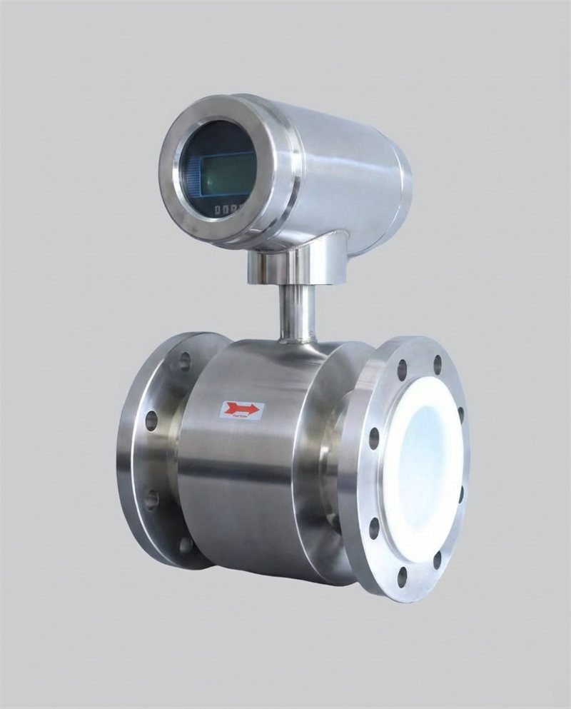
Electromagnetic flow measurement is commonly selected for conductive liquids with suspended solids because it can be full-bore with low pressure loss (material selection still matters).
Which meter is best for high-viscosity liquids?
Positive displacement and Coriolis are often considered, but the best choice depends on viscosity range, temperature dependence, allowable pressure loss, and maintenance strategy.
What’s the biggest cause of “bad readings” after installation?
Installation issues: wrong orientation, poor grounding/shielding, insufficient straight run, air pockets (not full pipe), vibration, and upstream valve disturbance.
How do I think about calibration and traceability?
Start by defining how the measurement is used (control vs custody transfer). Then define a verification method and frequency, and align it with traceability expectations in your quality or regulatory framework.
Is a more expensive meter always better?
No. The best meter is the one that meets requirements with the lowest total cost of ownership. A “premium” meter installed incorrectly can perform worse than a mid-range meter installed correctly.
What’s the fastest way to shortlist options for my plant?
Use a structured worksheet (fluid + pipe + flow window + accuracy + installation constraints). If you want help, Jade Ant Instruments can assist—start at www.jadeantinstruments.com.
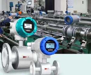
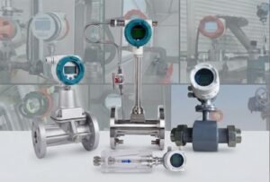
About Jade Ant Instruments
Jade Ant Instruments is a professional manufacturer and supplier of industrial flow measurement instruments, offering comprehensive solutions including electromagnetic flow meters, ultrasonic flow meters, vortex flow meters, turbine flow meters, Coriolis mass flow meters, and Thermal flowmeter. We provide not only high-quality products but also professional technical support and customized solutions to help you achieve accurate and reliable flow measurement.